The electrical part of the build….. some people like it and some people just dont know where to start. Luckily, im halfway decent with electrical. So Here is a consolidated post about everything i needed to get this thing started and running correctly.
First things first, lets talk about what i used. I have a wiring harness and E40 ECU from a 2006 GTO. Luckily everything just plugged right in and the only thing i really have to convert is the rear cam sensor to the front.
Just Getting the Motor Started
Ill start with the grounds. There are 3 grounds on the stock 2006 GTO wiring harness. Two of them are located at the front of the motor, one on the left and the other on the right side of the engine. The other is behind the driver side head. See the attached picture below.

Figure 1, 2, & 3: These black/red wires just need to get a GOOD ground. I grounded mine to the chassis ground on the driver side. That is about it for the grounds.
The positive voltage wires are pretty simple also. The pink and light green wires in figure 2 need fused 12V. I personally just put them both together on a 15A fuse and haven’t had any problems. One thing to note if you’re using the stock harness: there is a green and a light green wire in the harness shown in Figure 2. You must take some extra time to make sure its the LIGHT GREEN wire.
Also know that GM appeared to wire up each side of the motor (Injectors & Coils) with its own 15A fuse. If you put them together like i did and something blows up just know you were warned!


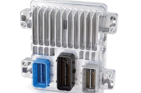
Here is what i did for the ECU wiring:
Blue Connector (C1):
If you use the stock wiring harness the only thing you really have to wire up is the C1 connector. Everything else should be already ran and ready to plug in like sensors and stuff.
- Pin 1: To Pin 6 for OBD2 Connector (See OBD2 Below For Reference)
- Pin 2: To Pin 14 for OBD2 Connector (See OBD2 Below For Reference)
- Pin 14: Power from ignition (C101 Pin 7 See Image Below)
- Pin 19: Power from ignition (C101 Pin 7 See Image Below)
- Pin 20: Constant Battery 12V (15A)
- Pin 36: Positive Voltage to Radiator fan relay (for ECU controlled radiator fans)
- Pin 45: Positive Voltage to Fuel Pump Relay.


For my Ignition wiring I connected my run position ignition (pin 7) to my engine electronics relay.
The Throttle: My engine uses the electronic throttle body which is wired up into the C1 connector. Here is what i did to wire it up.
On the C1 Connector:
- Pin 7: Connected to Pin 1 (See pedal wiring below)
- Pin 8: Connected to Pin 7 (See pedal wiring below)
- Pin 22: Connected to Pin 5 (See pedal wiring below)
- Pin 29: Connected to Pin 6 (See pedal wiring below)
- Pin 35: Connected to Pin 2 (See pedal wiring below)
- Pin 41: Connected to Pin 3 (See pedal wiring below)

OBD2:
The OBD2 port is pretty easy also.
- Pin 4: Ground
- Pin 5: Ground
- Pin 6: To Connector C1 Pin 1
- Pin 14: To Connector C1 Pin 2
- Pin 16: Positive 12V
See Below for the Diagram.


